Autonomous Catching Robot
Solo Project · In Development
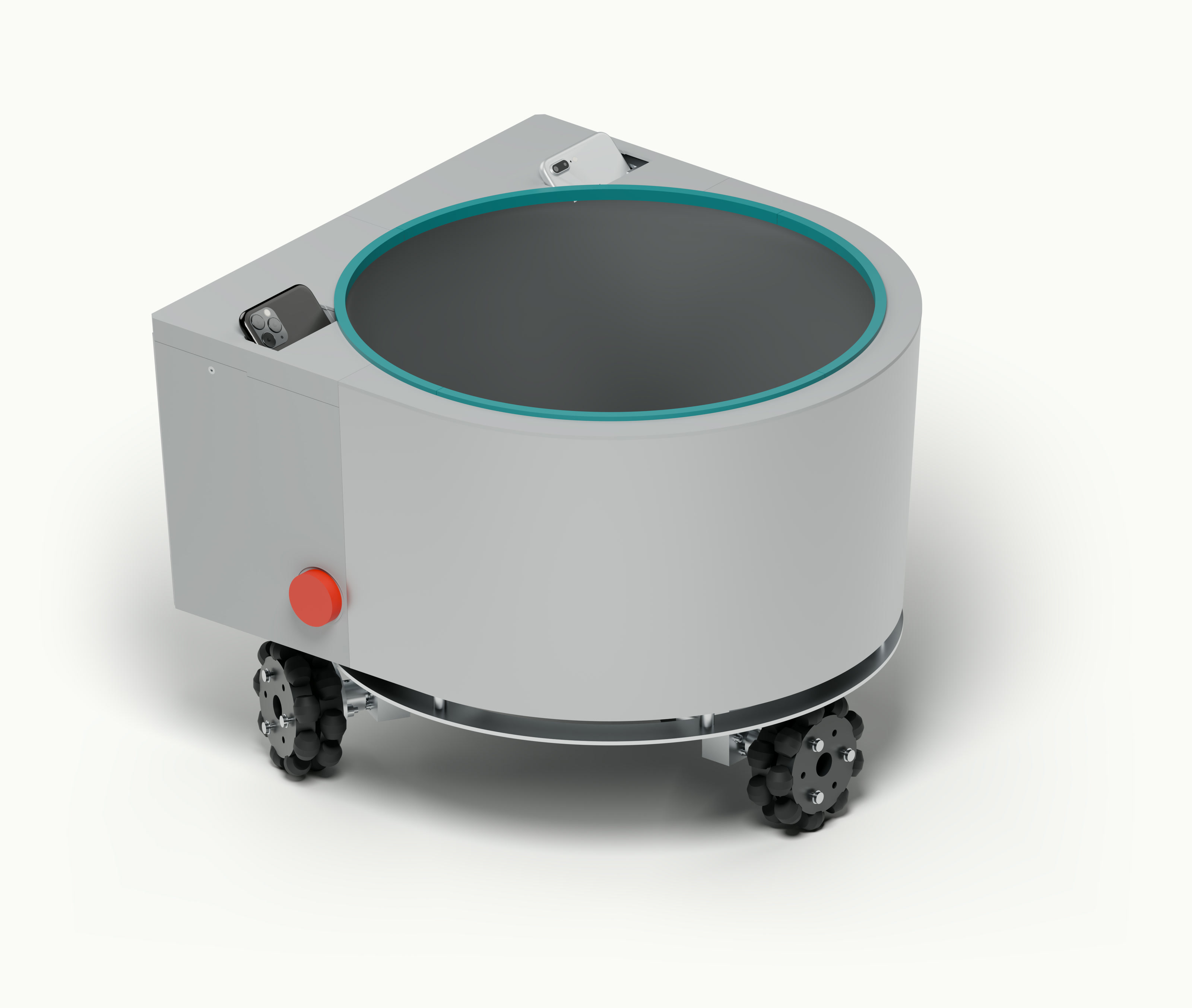
The Autonomous Catching Robot is a robotic bin designed to intercept a thrown tennis ball. The intended system uses two stationary phone cameras and an iOS app to estimate where and when to intercept it, with a Raspberry Pi planning the bin's movement. I developed the software using a stereo testing and calibration rig, then designed the complete robot around a circular catching opening and a rear electronics bay. Testing so far covers camera capture on each phone separately, predictions from recorded throws, and planner simulations; the complete robot remains unbuilt, and live paired operation is unverified. The central constraint is predicting accurately enough, and early enough, to accelerate toward the target and stop before the ball arrives.
Catch Geometry
The bin opening defines the combined error budget for perception and motion. The current CAD has a nominal 380 mm (15 inch) circular mouth. A tennis ball approximately 67 mm in diameter leaves about 156 mm of clearance on either side when centered. That is a geometric upper bound: prediction error, stopping error, rim contact, and rebound must all be considered.

Observing more of the flight can improve the trajectory estimate, but leaves less time for movement. For an ideal move that starts and ends at rest without reaching the speed limit, equal acceleration and braking split the movement window into two halves. Holding acceleration a constant, the ratio of reachable distances d for 300 ms and 400 ms is:
Losing a quarter of the movement window nearly halves the available reach. I therefore prioritized acceleration and braking over top speed.
Camera Rig
Stereo vision recovers depth by comparing the ball's position in two calibrated camera views. This addresses a weakness of a single view: an approaching ball can travel substantially in depth with little displacement across the image. My early monocular fits produced smooth trajectories but incorrect landing times. To develop and calibrate the stereo software, I mounted an iPhone 11 Pro Max and iPhone 7 Plus on a printed bar, with the lenses approximately 6.7 inches apart. I already owned both phones, and separate calibration accounts for their different optics and capture resolutions.

Stereo depth depends on both camera spacing and relative orientation. A wider baseline improves depth sensitivity but enlarges the assembly, which was constrained by the printer bed. In an early recorded throw test, the landing prediction differed by roughly 28 inches in depth from the landing position reconstructed from the stereo footage. I initially attributed this to insufficient spacing, but a checkerboard recorded during the same session exposed a mismatch between the stored camera rotation and the mounted phones. Recalibrating their relative orientation resolved the depth error without widening the bar. This made repeatable phone seating a measurement requirement, not just a mounting convenience.

The optical configuration must remain repeatable too. Calibration and recording need the same capture mode because sensor cropping changes between modes. In a later session, an unfocused ball appeared as a blur halo, biasing its estimated center. I recaptured with focus locked and treated focus and exposure settings as part of the measurement setup, rather than attributing the resulting error to the trajectory model.
Integrating the Cameras
The complete robot places the phones at opposite rear corners, with the camera modules exposed above the rim and the bodies recessed into the walls. Integral printed guides hold the phones 42 degrees from vertical and locate them against bottom stops. The slots have nominal clearance of 0.15 mm per side and face, with lead-ins for insertion and an open center for cooling. Either phone can slide out for charging without removing any other parts. Seating force, cooling, and calibration repeatability still need checks with the printed parts and actual phones.

Ball Tracking
Each phone locates the ball in its own images using background subtraction and the tennis ball's color to limit processing cost. This assumes stationary cameras and restricts the current detector to tennis balls. A ball that rolled to a stop initially remained a false target because it differed from the original background. I made the background adaptive while waiting for a throw, then froze it during flight to preserve the moving ball.

Detecting the ball does not establish that it has been released. Including motion while it is still in the thrower's hand biases the estimated acceleration away from gravity. I check for a sequence consistent with ballistic flight after release before using the observations for prediction.
Capture & Timing
At 240 fps, observations arrive about 4.2 ms apart. This sets the detector's throughput budget, not the total capture to prediction latency. I tested sustained camera capture and detection on each physical phone separately while powered over USB. The older phone initially processed at half resolution, then heated up and began dropping frames. Further downsampling let both phones maintain 240 fps without drops during these tests, while the newer phone retained more image detail. I accepted lower spatial resolution for consistent sampling; the effect on live trajectory accuracy remains to be measured.
The two camera streams also need a common time reference. Pairing observations from different instants introduces an apparent depth error even with correct geometric calibration. The phones exchange candidate ball positions and timestamps rather than video, and one combines the observations for trajectory prediction. I implemented clock synchronization and stage timing logs to distinguish capture, processing, and communication delays.
Trajectory Prediction
The prediction must identify where and when the ball descends through the height of the bin rim. I triangulate synchronized camera observations into 3D positions, then fit initial position and velocity under gravity with a fixed drag term chosen for the tennis ball recordings. Extrapolating that trajectory gives the interception position and arrival time. Current recordings and configuration use floor contact; interception at the rim requires setting the corresponding height and transforming the prediction into the chassis coordinate system.
To evaluate how early predictions stabilize, I replay recorded throws with progressively longer observation windows. For each throw, I fit the complete trajectory to estimate a reference landing position and contact time, then compare predictions from the partial recordings against that reference. Scoring requires acceleration consistent with flight, low fit residuals (discrepancies between observations and the fitted path), and enough observations before the prediction cutoff.
At 400 ms before reference contact, 19 throws met these criteria; their predicted landing positions differed from the reference by a median of approximately 1.7 inches. This is an offline convergence result for selected tracks, not a detection success rate. It also does not establish independent landing accuracy: the partial and complete fits share recordings and a model, so calibration errors can affect both. Separate landing measurements are needed before comparing this result with the bin's clearance budget.
Drivetrain & Motion Control
The chassis uses three omni wheels arranged 120 degrees apart to translate without a steering maneuver. Eliminating that delay preserves more of the movement window, but omni rollers sacrifice traction compared with conventional rubber wheels. The motors hang below one aluminum chassis plate; the rear pair sit farther aft to support the electronics bay. Acceleration and braking under representative load must be measured before calculated reach can be treated as achievable.

Each motor bolts to a short aluminum hanger that attaches directly to the chassis plate. A flanged hub connects the wheel to the gearbox's D-shaped shaft; a radial set screw retains the hub, and three through-bolts clamp the wheel to its flange. This separates the wheel connection from the motor mounting so either can be serviced without replacing the other. The gearbox bearings' capacity for the overhung wheel load still needs confirmation.

The predicting phone sends the interception position and arrival time to the Pi, with acknowledgments to confirm receipt. While the cameras are stationary, the app can refine this target. Once motion is detected, I suppress further visual updates because the calibrated camera poses and background no longer apply. The Pi then follows the last target, and the app resumes tracking after the chassis settles.
The Pi planner converts the target into wheel speeds and an acceleration and braking profile, using encoder odometry to estimate position and velocity. To test this handoff, I connected the same Swift prediction core used by the app to the planner through replay of recorded detections. Repeating identical inputs isolates integration failures from variation between throws. This exposed dropped target messages when incoming bursts exceeded the planner's packet handling per cycle, which I corrected in the receive path.
In separate planner simulations, repeated target commands exposed a different failure: rebuilding each profile from rest repeatedly restarted acceleration and nearly stalled the simulated robot. I changed replanning to account for current velocity. Targets inside the stopping distance trigger braking first, preserving a physically feasible transition.
I wrote the wheel speed controllers for the Pi, avoiding a separate controller in the planned hardware. That choice depends on reliable encoder readings and control timing under load, with a microcontroller retained as a fallback.
Hardware & Construction
The mechanical design combines manufacturing processes to avoid printing a large, mostly empty enclosure. A rolled 1 mm 5052 aluminum skin forms the curved front and side returns. A 3 mm aluminum chassis plate carries the three geared motor and wheel assemblies. Printed rear corners integrate the phone guides and service-panel rails, while routed sheet parts locate the formed skin and bowl.
Inside, a formed PETG backing joins a separate PETG floor and supports a shaped closed-cell EVA liner. The bowl widens toward the circular mouth, and smooth transitions beside the phones guide the ball inward without a ledge underneath. The rear bay occupies the flat side of the D-shaped envelope, keeping electronics outside the catching cavity. The liner's rebound behavior and the shell joints still need prototype tests.

Each printed rear corner combines the sidewall, phone guides, and rear service-panel rail. A separate upper cover closes the bay while leaving the phone withdrawal path open. The broad sidewalls use a continuous 2.4 mm skin, with thicker material at the screw seats and guides. Metal posts and battery brackets bear directly on the chassis plate; local standoffs support the separate bowl floor.

The Raspberry Pi, motor drivers, protection hardware, and both batteries share the rear service bay. A USB power bank supplies the Pi and logic; a separate 3S lithium-polymer pack supplies the motors. The phones use their own batteries. A single passive rear cover slides in fixed U-shaped guides and locks with a thumb screw. All electronics stay on the fixed structure, so opening the cover does not pull on a wiring harness.

The build sequence starts with one motor, driver, and wheel on a test rig, ballasted to its expected share of chassis weight. This lets me measure acceleration and braking on the actual floor before committing to the remaining drivetrain parts. Bench tests will also check encoder counts and control timing under processor load. A bench supply is sufficient for initial testing, but current limiting would make the measured acceleration a lower bound; those measurements must be repeated on the intended battery before setting the planner's motion limits.
Integration & Testing
Verification so far covers recorded camera data, planner simulations, and software replay. Live paired camera streaming and throws through the complete app remain unverified. Once the hardware is assembled, I will recalibrate the mounted cameras and verify the motor power cutoff and my communication watchdogs with the wheels raised. Tethered tests will then check the software travel boundaries before unrestricted movement, with speed increased gradually.
Stopping accuracy tests in several directions will establish how much of the clearance budget the assembled drivetrain consumes. Separate drop tests will check whether the liner retains the ball before attempting live catches. These tests return to the original catch constraints: arrive before the ball, stop within the shared error budget, and absorb the impact.