Waterproof Flashlight
Solo Project
View CAD model →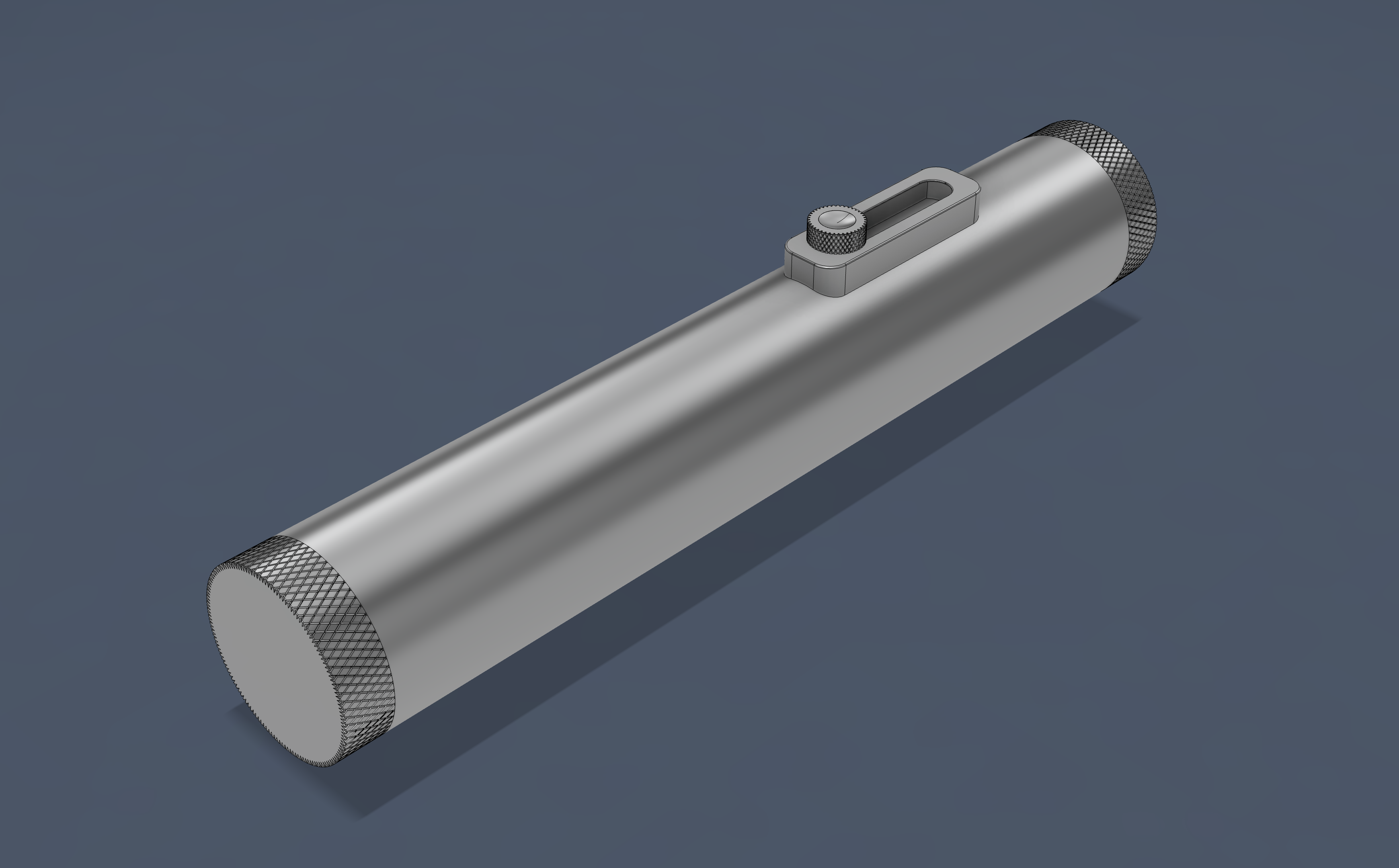
I handled the full design cycle myself, including parametric CAD in Fusion, a custom MCPCB, drop impact FEA, and the manufacturing plan. The central design problem was keeping it waterproof while having a physical slider; I solved this with through wall magnetic sensing, where a 1/r³ field falloff through a 2mm aluminum wall bounded how far the slider could travel. The rest was integration hell, where tolerances compound inside a 22mm bore and fixing one interference tended to shift another.
The Concept
I wanted to design a flashlight from scratch, handling everything myself: the mechanical design, the electronics, the thermals, and the manufacturing plan. A flashlight felt right because the form factor is constrained enough that every decision interacts with every other; the PCB has to fit the bore, the wall thickness affects both structural strength and magnetic sensing range, and so on. I've always noticed that flashlights tend to be poorly designed as objects to hold and use. The button is usually on the tailcap, making one handed control awkward, and most of them look like they belong in a drawer. I wanted to make something worth leaving out.
I enjoy older hardware that has a nice tactile quality to it, and I wanted the flashlight to have that same character. I designed the surfaces purposefully; the head cap, tail cap, and slider knob are diamond knurled for a nice texture at touch points, while the rest of the body is finished smooth for comfort in the hand.
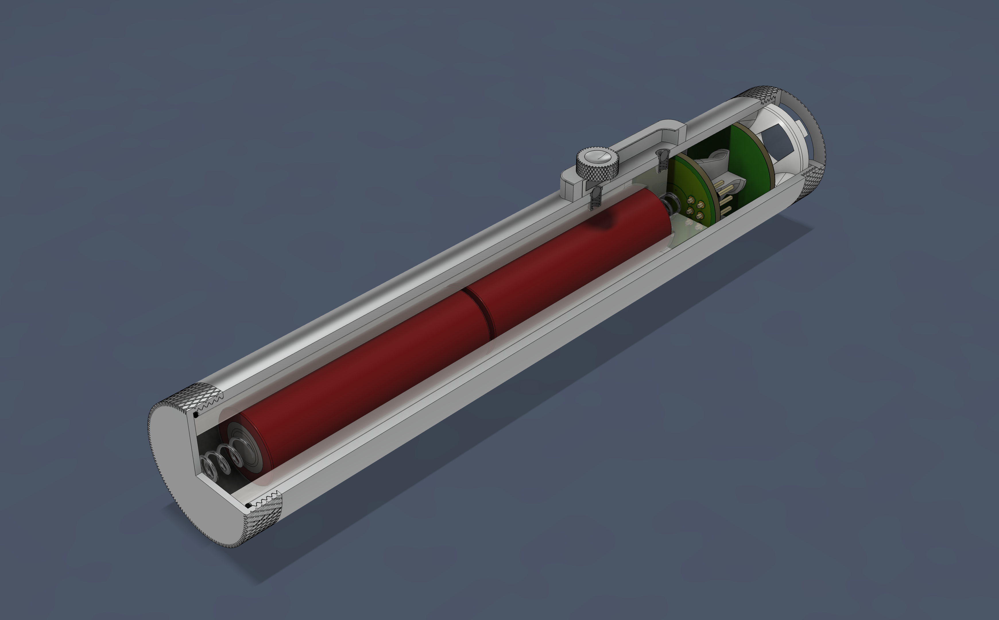
The central feature is a sliding brightness control. I knew I wanted this flashlight to be waterproof, so the brightness control sits on the outside of the body with no physical penetration through the wall. Instead, a neodymium magnet in the slider passes its field through the aluminum (which is non-ferromagnetic and doesn't attenuate the field) to a hall effect sensor on the PCB inside. The user slides a knob along the body for continuous one handed dimming, while the microcontroller reads the changing field strength and maps it to LED brightness via PWM. There is no physical connection between the exterior control and the sealed interior, so the body stays fully waterproof. I originally wanted a perfectly cylindrical body, but making the outer diameter large enough everywhere to fit the slider channel would waste a lot of material. Instead I brought the slider outside on a minimal raised flat and kept the rest of the body, including both end caps, flush with the cylindrical profile. The AA battery format was a deliberate tradeoff; rechargeable lithium cells would be more energy dense, but AAs are universally available and keep the design accessible.
Body
The body is turned from 6061-T6 aluminum on the lathe, with the T-slot channel for the slider milled into a raised flat section along one side.
The head cap and tail cap both thread into their respective ends and sit flush with the body profile; I didn't want protruding caps breaking the clean lines. Getting a truly flush fit required machining the counterbore that each cap seats into to a precise depth, so the cap's outer face aligns with the body surface. I held this depth to ±0.05mm. An O-ring sits in each cap, sized per Parker O-Ring Handbook specifications for about 10% compression on a standard AS568 O-ring, sealing the joint. With both ends sealed, the body forms a fully enclosed envelope. The only other penetrations are the two ball detent holes in the slider channel, which I plan to seal with RTV silicone on the bore side before final assembly.
The body wall is 2mm throughout, which keeps the flashlight as thin as possible while maintaining a uniform outer diameter. The wall serves as structural support, waterproof barrier, magnetic sensing interface, and heatsink all at once, avoiding the need for separate layers that would bulk up the body. Going thinner would bring the magnet closer to the sensor and improve signal strength, but would reduce structural margin and make machining more difficult; 2mm was the balance point.
I parameterized all core dimensions in Fusion early on; I've been burned before by designs where changing one dimension means hunting through dozens of sketches to find everything that depends on it. Having bore diameter, wall thickness, battery length, etc. all linked meant that when I adjusted the counterbore by 0.25mm for a flush surface, everything downstream updated on its own.
Slider & Dimming
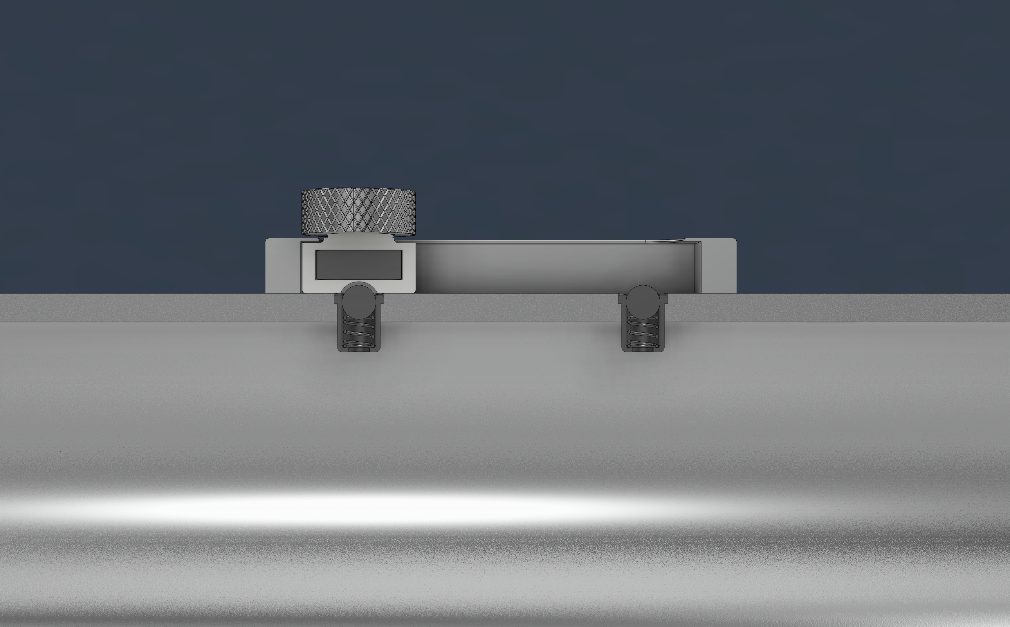
A T-slot channel machined into the raised flat section constrains the slider to smooth linear motion with no play or wobble. The consistent travel resistance is essential for replicating the fader like feel I was going for. The slider carries a 6 x 2mm N52 neodymium disc magnet; I chose the 6mm diameter over 4mm and 5mm options because the larger disc produces a stronger field at the sensor and a wider detection zone, which smooths out the brightness response as the slider moves. N52 is the strongest commercially available neodymium grade, and with the 1/r³ falloff working against the design, every bit of field strength matters. The magnet is oriented with its poles along the flashlight axis, aligning the field with the DRV5053VA hall effect sensor's sensitive axis on the PCB. I chose the DRV5053VA specifically because it is the most sensitive variant in its family at 45mV/mT; at the far end of the slider travel, the field is weak enough that a less sensitive sensor would not register it above the noise floor.
I plan to 3D print the magnet holder by pausing the print partway through, placing the magnet, and resuming; this fully encases the magnet without seams or a separate lid, keeping the protrusion from the body as small as possible. The slider's bottom face conforms to the flashlight body's cylindrical surface via a boolean cut against the body geometry in Fusion. This means it only fits in the correct orientation, which is a deliberate design for assembly choice; there is no wrong way to install it.
The magnetic field from a dipole falls off as 1/r³, which turned out to be the tightest constraint on the whole design. At 3mm (directly beside the sensor through the wall), the magnet produces about 50mT. At 25mm, the field is only 0.2% of that:
Multiplying that ratio by the 50mT at 3mm gives the field at 25mm: 0.002 × 50mT ≈ 0.1mT. The DRV5053VA hall sensor converts field strength to voltage at 45mV/mT:
The ATtiny25V reads this with a 10 bit analog to digital converter (ADC), which divides the 3.3V reference into 1024 discrete steps. One step is the smallest voltage change the microcontroller can distinguish:
The 4.5mV sensor output at 25mm is only about 1.4 steps:
That is barely one step above zero, which means the microcontroller can hardly tell if the magnet is there or not. Beyond 30mm the signal disappears entirely.
I originally wanted 2 to 3 inches of thumb travel for a more comfortable sweep. At 50mm, I calculated the straight line distance to the sensor at 50.1mm, which produces less than one ADC count. I spent a while exploring ways to extend range. A ramped channel floor could work like a wedge, converting the slider's long axial travel into a much shorter radial displacement of the magnet; 50mm of thumb movement would translate to 2-3mm of magnet movement toward or away from the sensor, taking advantage of the steep 1/r³ sensitivity to small radial changes. But the ramp requires the channel to be much deeper at one end, which would add width to the body. I also considered adding an op-amp between the hall sensor and the ADC to boost weak signals, and placing two sensors spaced along the bore so each one only needs to cover half the range. Both of these added volume/complexity without enough benefit, so I settled on 25mm of travel with a single sensor.
Detents
Designing the detent feel was one of the more involved parts of the slider. I wanted a satisfying click at the off and full brightness positions, to let the user know they've hit the endpoint without looking and without requiring much force to push past. Two ball detents in the channel floor provide this. The dimples on the slider underside are 2.9mm diameter and 0.825mm deep; I tuned the depth to balance click strength against sliding effort. The press fit plungers I ended up with have a lighter spring force than the threaded plungers I originally specified, which actually works in the design's favor; it produces a gentle snap that doesn't interrupt the sliding motion.
Finding the right detent hardware took several iterations, driven by the constraint that the detent holes go all the way through the body wall. My first choice was a threaded ball nose spring plunger from McMaster (3408A88, #4-48 UNF). However, the threaded hole exits into the bore, and I quickly realized there is no way to orient a screwdriver radially inside a 22mm bore to install the detents. Hex socket drive plungers seemed promising since I thought the hex might be accessible from the side, but it turned out the socket is on the back end. Even a 90 degree offset screwdriver wouldn't fit the clearances I needed. I ended up with press fit ball plungers, which install from the channel side with no tools needed inside the bore.
The press fit hole is undersized by 0.01mm to start; I went conservative since I can always widen the bore but can't add material back. I plan to seal each through hole with RTV silicone on the bore side before installing the PCB.
Knob
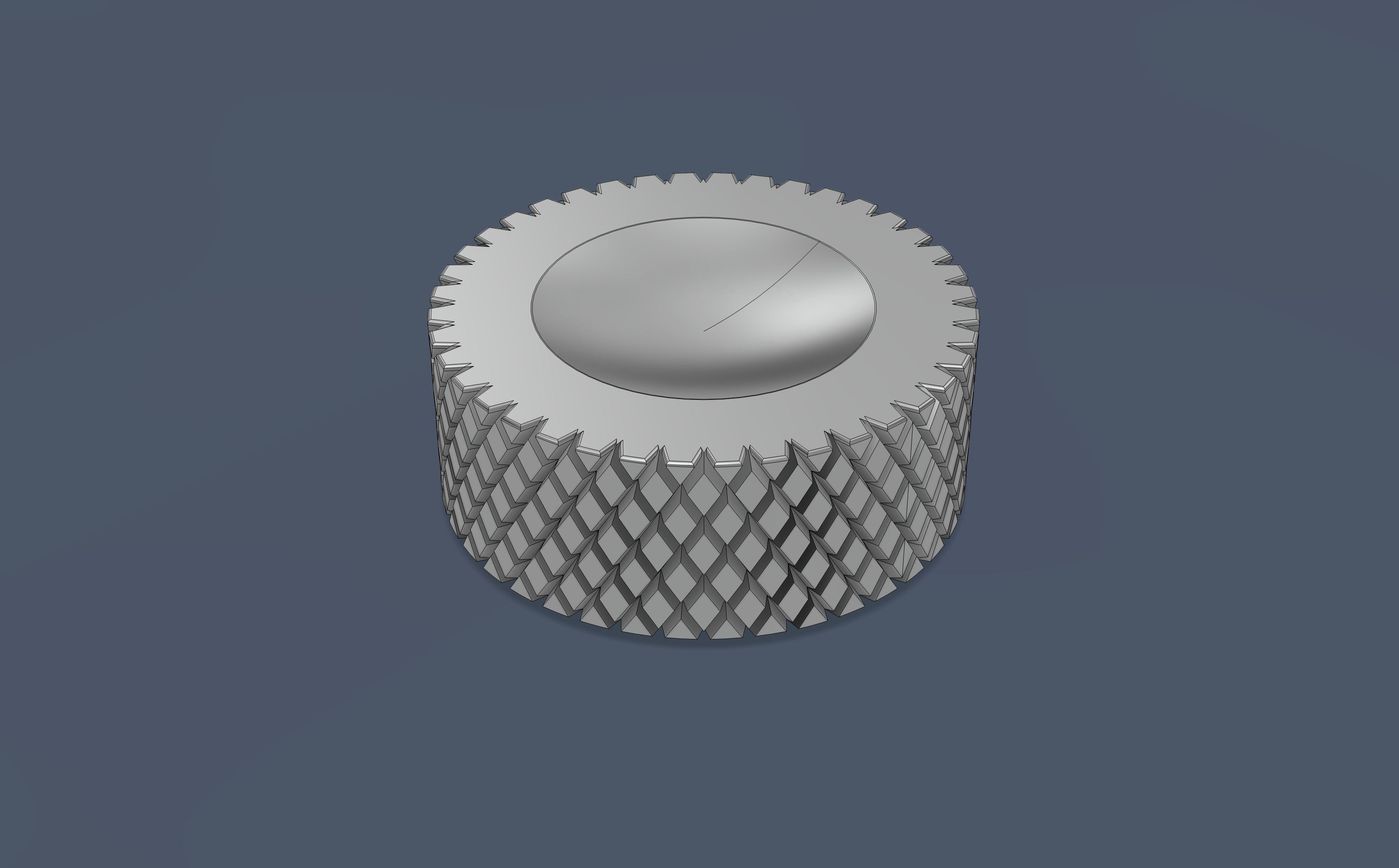
The knob is turned from 6061-T6 aluminum on the lathe with a diamond knurl, matching the body material for a cohesive look. I considered brass for the visual contrast, but it looked out of place when everything else is aluminum. The knob screws onto an M5 threaded post on the slider body. I initially considered M3, but the knob takes lateral force from thumb pressure during sliding, and an M3 post in a plastic prototype would snap under repeated use. M5 gives a 5mm shear section that handles the load comfortably. The threaded connection also means the knob is swappable; I prototyped ergonomic profiles in PLA before committing to the final aluminum version.
I modeled a thumb divot in the top using a revolved spline (chosen over tangent arcs and conic curves because splines give direct control over the tangent direction at each point). My first few attempts left a visible sharp point at the bottom of the divot where the curve meets the revolve axis. I did some research into surface continuity and found the difference between G0 (edges touch), G1 (tangent direction matches), and G2 (curvature matches). Applying G2 continuity at the boundaries where the spline meets the knob face eliminated the ridge entirely, producing a perfectly smooth concave rest.
Electronics
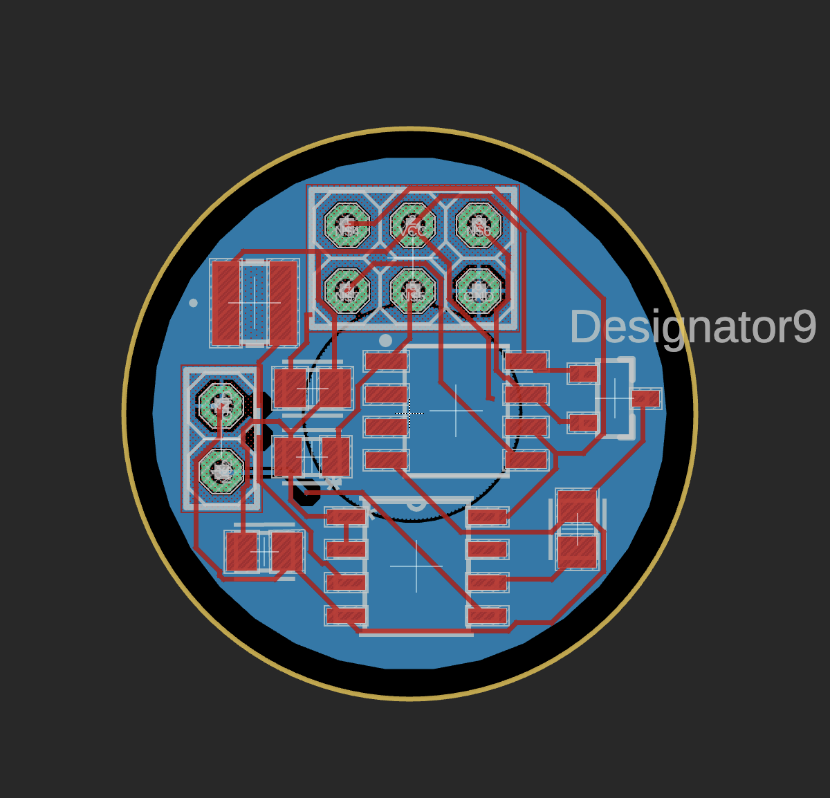
The PCB is designed in Fusion's electronics workspace rather than a standalone EDA tool, because having the schematic, board layout, and mechanical CAD in the same environment let me verify PCB clearances against internal components and dimensions without exporting between programs. The board is built around three main components: an ATtiny25V microcontroller, the DRV5053VA hall effect sensor, and an N-channel MOSFET for PWM LED driving. The entire package lives inside the sealed bore with no wiring through the body wall. I used the autorouter for initial trace placement and then refined critical paths by hand; the analog line from the hall sensor to the ADC pin needs to be short and routed away from the high current PWM traces to avoid noise coupling. I split the ground pour into two zones: a central VCC pour and an outer GND pour, to keep the power and ground return paths separated. All components are surface mount to keep the board thin.
The LED generates significant heat, so the PCB is a metal core board (MCPCB) that makes direct contact with the bore wall, using the aluminum body as a heatsink. This means the board width is essentially fixed at the bore diameter, and component placement has to work within that constraint. The hall sensor sits at the board edge, aligned with the slider channel; even a 1mm offset shifts the brightness response curve noticeably. Having the PCB in the same Fusion file as the mechanical assembly meant I could catch interference issues directly rather than discovering them after ordering the board.
For the PCB spacer, I used Fusion's generative design workspace. I defined five connection points between the spacer and the bore wall while keeping the PCB and its components as keep out regions. The solver produced an organic shape that holds the board in alignment without interfering with any components; I plan to 3D print it.
Analysis
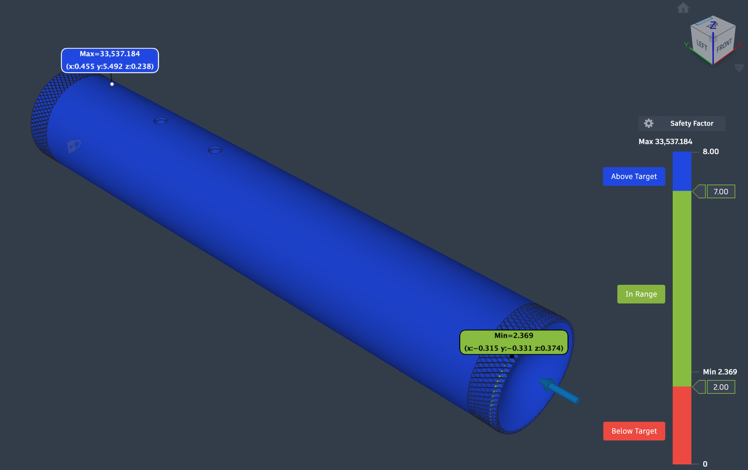
I ran a static stress FEA to simulate dropping the flashlight from 1.5 meters onto a hard surface. The flashlight weighs 227g, and a typical shock multiplier for a metal object hitting concrete from that height is around 100 to 150g. Using 110g as a conservative estimate:
I rounded this to 250N and applied it to the tail cap face. The head cap was fixed, and I set bonded contact between the threaded surfaces of the tail cap and body so the solver correctly models how the threads transfer load into the body wall.
The minimum safety factor is 2.369, located at the thread roots where the body wall is thinnest (about 0.2mm between the thread root and the bore). This initially seemed like a problem, but the threads interlock with the cap; the cap's thread peaks fill exactly where the body's thread roots are thin, so the effective wall thickness at any cross section through the threaded area is closer to the full 2mm. The bonded contact captures this, and the result confirms the design holds with margin. The rest of the body is deep blue on the plot, meaning the safety factor is well above 8 everywhere else. Since the minimum safety factor is over 2, the design would also survive a 150g shock multiplier (the upper end of the expected range) without yielding.
The 2mm wall thickness was itself a tradeoff. Thinner walls would bring the magnet closer to the sensor and extend the usable slider travel, potentially making the 50mm (2 inch) range viable. But thinner walls reduce the safety factor, make machining harder, and weaken the waterproof envelope. The magnetic field calculation and the FEA together defined the design space from both sides: the 1/r³ falloff set a minimum wall thickness below which the signal is strong enough for longer travel, and the structural analysis set a minimum wall thickness above which the body survives a drop. 2mm sits in the overlap where both constraints are satisfied, even though it limits travel to 25mm.
Battery life at full brightness with a 1W LED drawing approximately 350mA is about 7 hours on two AA cells at 2500mAh. The microcontroller and sensor draw microamps by comparison. PWM dimming at lower settings extends this proportionally.
Integration Hell
When I brought all the individual parts together in the assembly, a lot of small issues surfaced that I would not have predicted from the individual parts. Components that fit fine in isolation would interfere with each other, tolerances would compound in unexpected ways, and fixing one constraint would shift another. These are the kinds of problems that only show up when everything shares the same 22mm bore, and working through them took more time than designing any single subsystem.
Manufacturing will involve lathe turning and knurling for the end caps and knob, milling the T-slot channel, press fitting the detents, sealing with RTV silicone, ordering the assembled MCPCB from PCBWay, and 3D printing the magnet holder and spacers.