Point to Point Communication
Team Lead
View CAD model →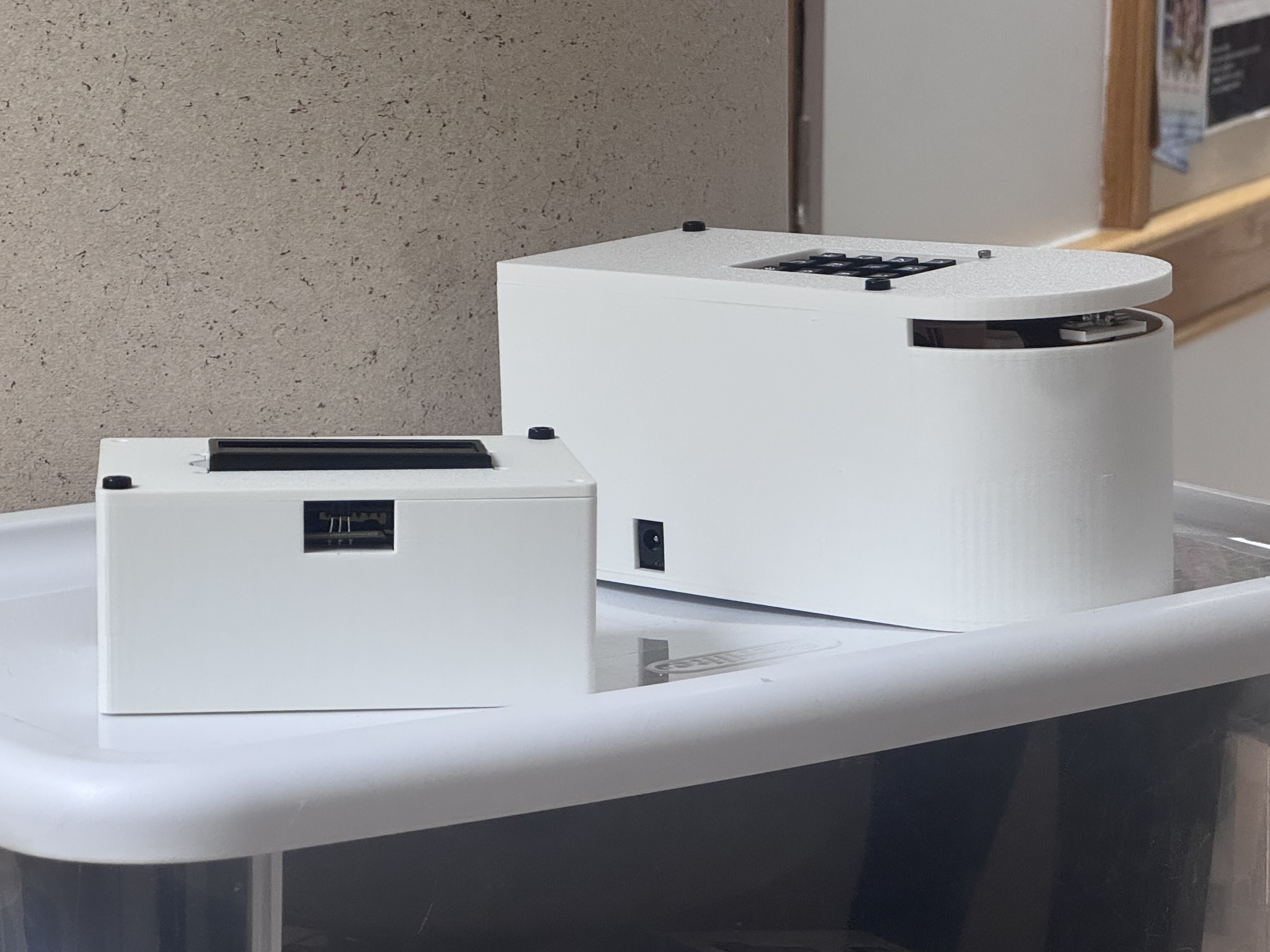
I led a small team to build a directional infrared messaging system, originally meant for a restaurant where a host stand sends table numbers to kitchen stations without shouting. The constraint was 15mW optical only with no RF, so the transmitter has to physically rotate to address each receiver position; we mounted only the IR emitter on the rotating platform to reduce motor load and speed up repositioning. We started with a visible laser and switched to IR after the laser's narrow beam missed the receiver on small pointing errors. Final hardware hit 100% message accuracy at 9 meters, well past the 1.5 meter requirement.
The Concept
The goal was a directional messaging system for a restaurant, where a host stand sends table numbers to kitchen stations without shouting across the room. The class it was built for (EK210 at BU) specified optical communication at 15mW with no RF. Unlike RF, light only goes where you point it, which made the pointing mechanism as important as the communication protocol; the transmitter has to physically rotate to address different receiver positions.
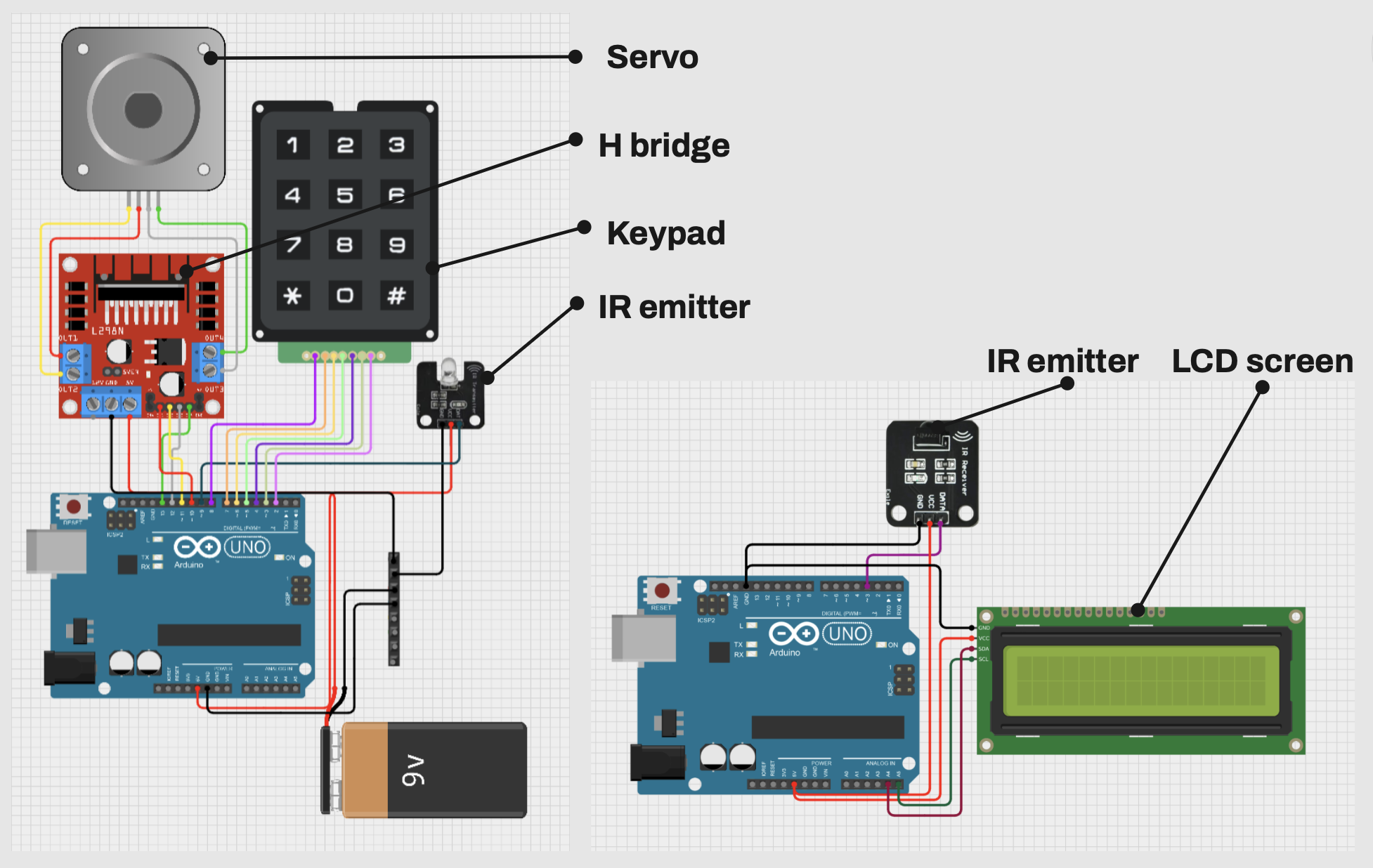
We started with a visible laser, which seemed like the obvious choice. It didn't last long; the beam was so narrow that small pointing errors from the rotating transmitter caused a total miss at the receiver, and ambient light washed out detection. Infrared with a wider beam angle was much more forgiving. The 38kHz modulation on the carrier lets the receiver reject ambient light, and a matched 780 to 1050nm photodiode filters everything outside the signal band.
Messages use the NEC protocol. Each keypad press is converted to a hex value, sent through a KY-005 IR emitter, and decoded on the receiver's KY-022 module for display on a 16x2 LCD. The receiver auto clears after 4 seconds, and a 600ms gap between presses inserts a space so users can send multi digit numbers as separate values.
Transmitter
The transmitter houses an Arduino Uno, NEMA 17 stepper, L298N motor driver, 12 button keypad, and IR emitter. Rather than rotating the entire enclosure, only the IR emitter sits on the rotating platform, which reduces the motor load and allows faster repositioning across the 135 degree range. The * key enters a rotation angle, # sends the message.
Homing was a problem early on. The stepper has no absolute position reference, so after a power cycle it doesn't know where it's pointing. We added a manual calibration routine on startup where the user zeros the emitter to a known position before entering angles. It works for a demo, but it's the kind of thing that wouldn't survive daily use.
Housing Design
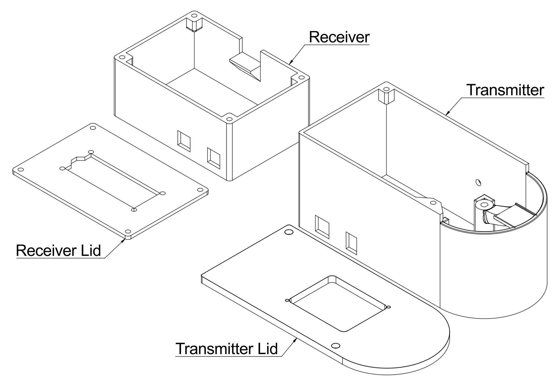
Both housings are 3D printed in PETG. The first iteration used identical 84 x 120mm rectangular enclosures for both units, but once the rotating emitter was integrated the transmitter needed a curved front face that follows the emitter's arc through its sweep.
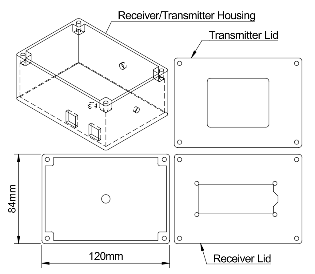
An intermediate cylindrical design worked mechanically but was much larger than necessary. The final transmitter conforms to the internal components: a rectangular section for the electronics with a semicylindrical front for the emitter. The receiver stayed simple, a rectangular box with cutouts for the sensor and LCD.
Performance
Testing showed 100% message accuracy up to 9 meters, well beyond the 1.5 meter requirement. Reliability dropped past that from IR power falloff and ambient interference. Angular tolerance was about 10 degrees, giving reasonable margin for imprecise aiming.
Total power draw is approximately 1W during typical operation, assuming 60% idle, 30% IR transmission, and 10% motor duty. The NEMA 17 at 350mA per phase accounts for most of the consumption but only runs during repositioning.
Reflection
The main limitation is that communication is one way. The transmitter has no confirmation that the receiver got the message, which matters if someone walks through the beam mid transmission. Even a simple acknowledgment LED on the receiver that the transmitter's photodiode can detect would close the loop. The housings also aren't sealed; since it is meant for a restaurant environment, I would have liked to make it waterproof but ran out of time.